Networks
The Networks page lets you manage virtual private networks that can be used by your local and cloud virtualization. Once created, virtual machines can be attached to these networks, and they will be able to communicate with each other, regardless of their physical location.
Conceptually, Slide Networks are similar to an Azure Virtual Network or an AWS VPC, though specifically designed for disaster recovery purposes.
There are two types of networks:
- Disaster Network: A Disaster Network provides a router with its own IP address and netmask (e.g. 10.0.0.1/24), and optionally a DHCP server, Internet access, Client VPN using WireGuard, as well as port forwards.
- Bridged Network: A Bridged Network creates a layer 2 network that attaches to the local network of a Slide Box. Any local or cloud VM that you attach to this network will receive an IP address from your own router. You'll even be able to print on your local printer from a Slide cloud virtualization.
Disaster Network
A Disaster Network creates a virtual network across all the attached virtual machines that offers a router, DHCP server, Internet access, VPN access, as well as port forwarding. You can think of it as a remote site with its own subnet (e.g. 10.80.0.0/24), except that you can attach VMs from any Slide Box or cloud VM to it.
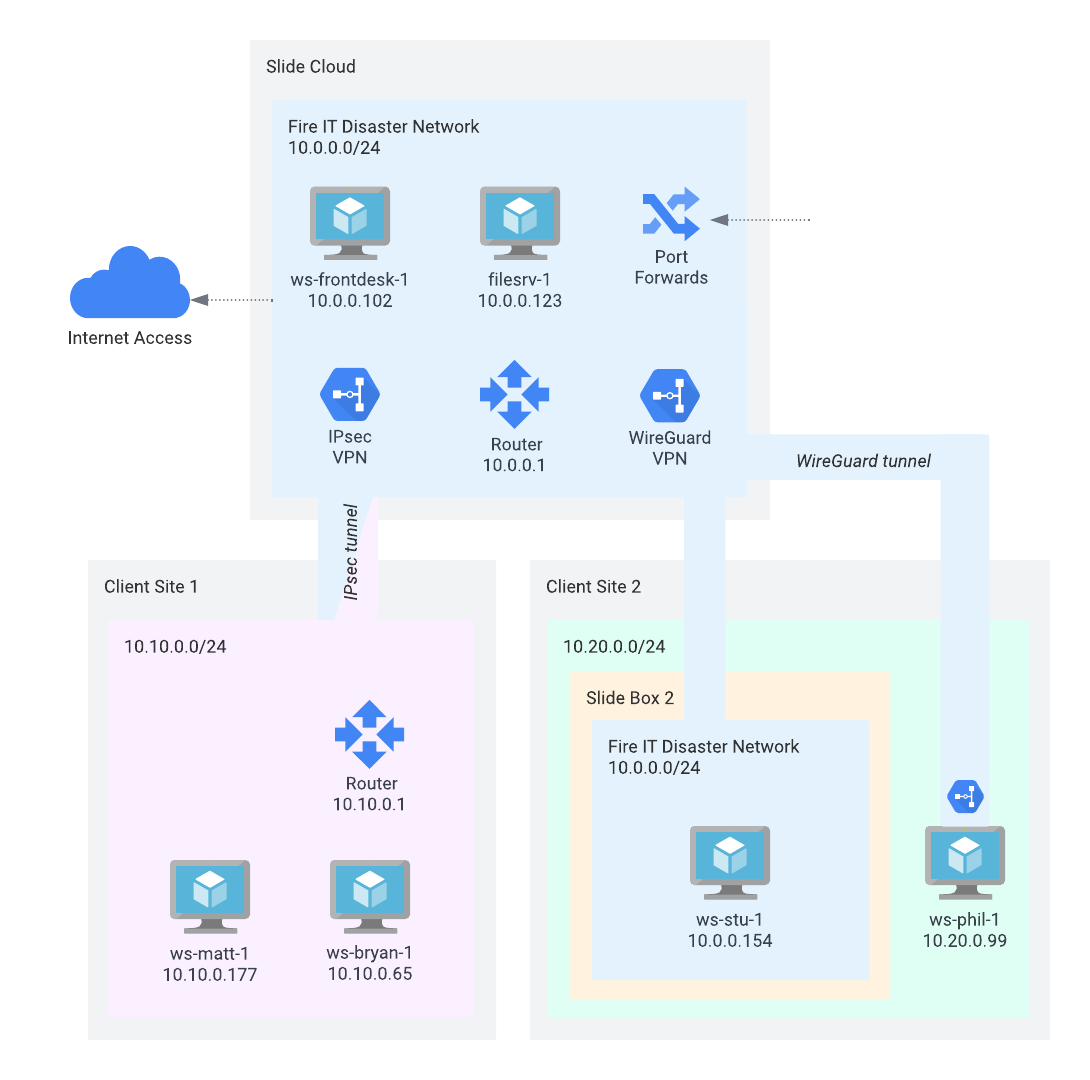
In the example above, a disaster network "Fire IT Disaster Network" was created with the subnet "10.0.0.0/24". There are two VMs in the Slide Cloud (ws-frontdesk-1 with 10.0.0.102, filesrv-1 with 10.0.0.123), and two connected client sites:
- Client Site 1 has subnet 10.10.0.0/24 and is connected to the disaster network via an IPsec site-to-site VPN through the site's router. The two workstations ws-matt-1 and ws-bryan-1 can seamlessly access the VMs in the disaster network.
- Client Site 2 has a Slide Box with one VM attached to the disaster network (ws-stu-1 with 10.0.0.154). The workstation ws-phil-1 with 10.20.0.99 is not part of the network. To communicate with the VMs (e.g., to connect via RDP or to a Windows Share), a WireGuard VPN has to be set up. Alternatively, you can set up port forwarding to expose services on the VMs to the Internet.
You can find more examples of how to use Disaster Networks in the Use Cases section.
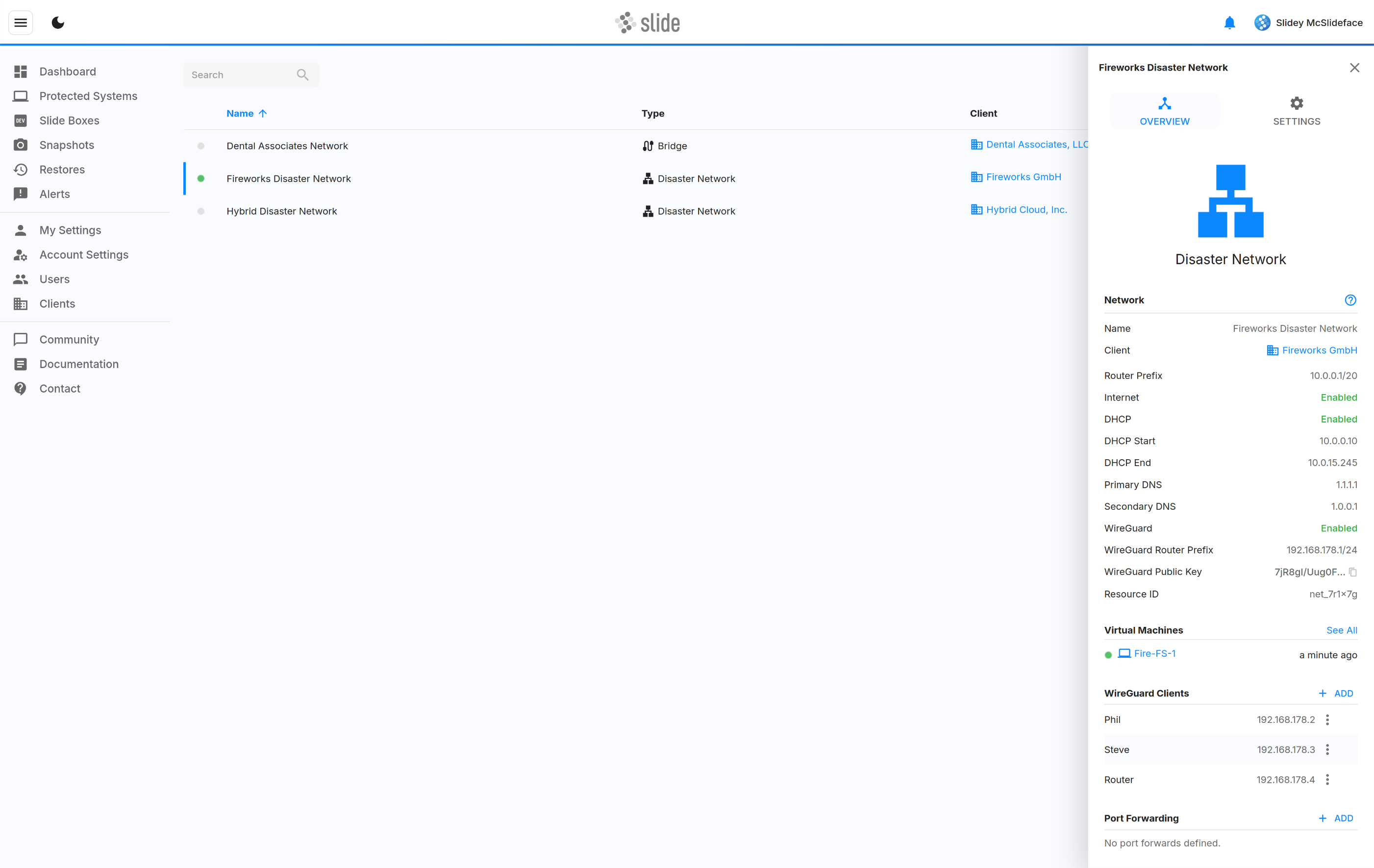
Creating a Disaster Network
You can create a Disaster Network by clicking on the "Create Network" button in the top right corner:
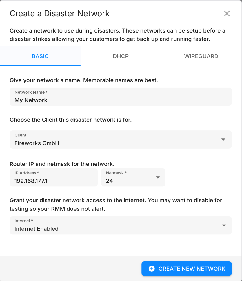
When creating a Disaster Network, you can specify the following options:
- Name: The name of the network.
- Client: A client that this network is associated with. Choosing a client will restrict the protected systems that virtualizations can be attached to. We highly recommend setting a client to avoid accidentally attaching a VM to the wrong network.
- Router IP/Prefix: The IP address and prefix of the router. This defines the subnet of the network, as well as the router's IP address. You can pick any private network prefix, i.e. any networks contained within 10.0.0.0/8, 172.16.0.0/12, or 192.168.0.0/16. The router IP address must be within the specified prefix. The default is 192.168.177.1/24.
- Internet: If enabled, VMs in the network will have access to the Internet. If disabled, VMs will be able to communicate with one another, but not with the Internet.
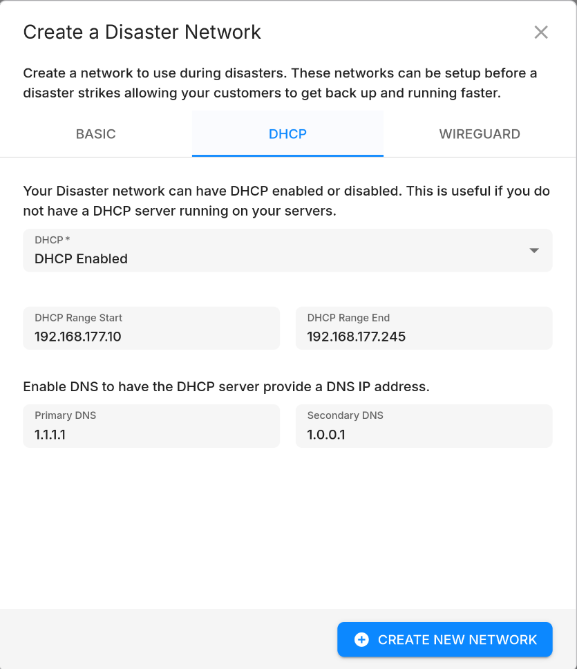
- DHCP: If enabled, a DHCP server will be created on the network. This means that VMs attached to the network will receive an IP address automatically. If disabled, you will need to assign IP addresses manually. You can configure the DHCP range, as well as the DNS servers that the DHCP offer will contain.
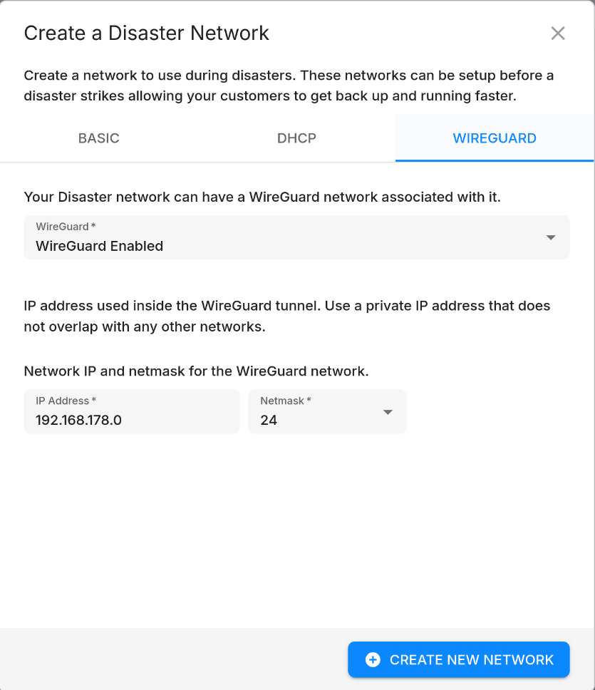
- WireGuard: If enabled, a WireGuard VPN server will be created on the network. This allows you to connect to the network from anywhere in the world using WireGuard. Pick a WireGuard server IP address, and a network prefix for the WireGuard peers. The network prefix should be distinct from the router prefix you pick. You can configure WireGuard clients after creating the network.
To create IPsec connections to the network, create the network first, and then add the IPsec connections in the sidebar of the network page.
Attaching Virtual Machines
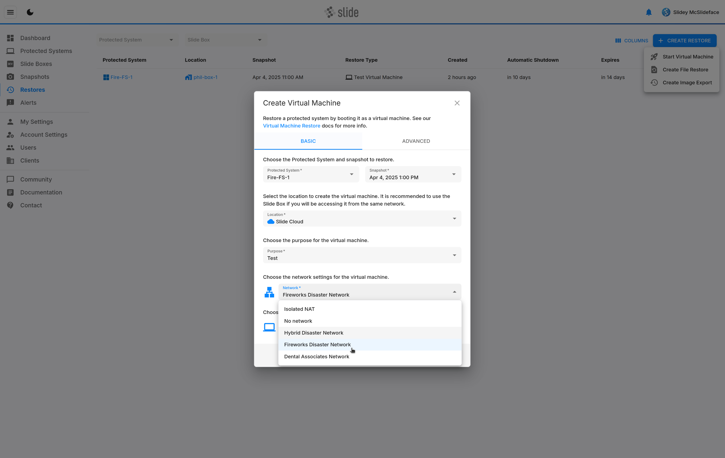
Once a network is created, use the restores page to create a new Virtual Machine. In the create dialog, choose the network you just created and start the VM.
The physical location of the VM does not matter, as long as it is attached to the network. It can be on any Slide Box, or in the Slide Cloud. The VM will be able to communicate with other VMs in the network, regardless of their physical location.
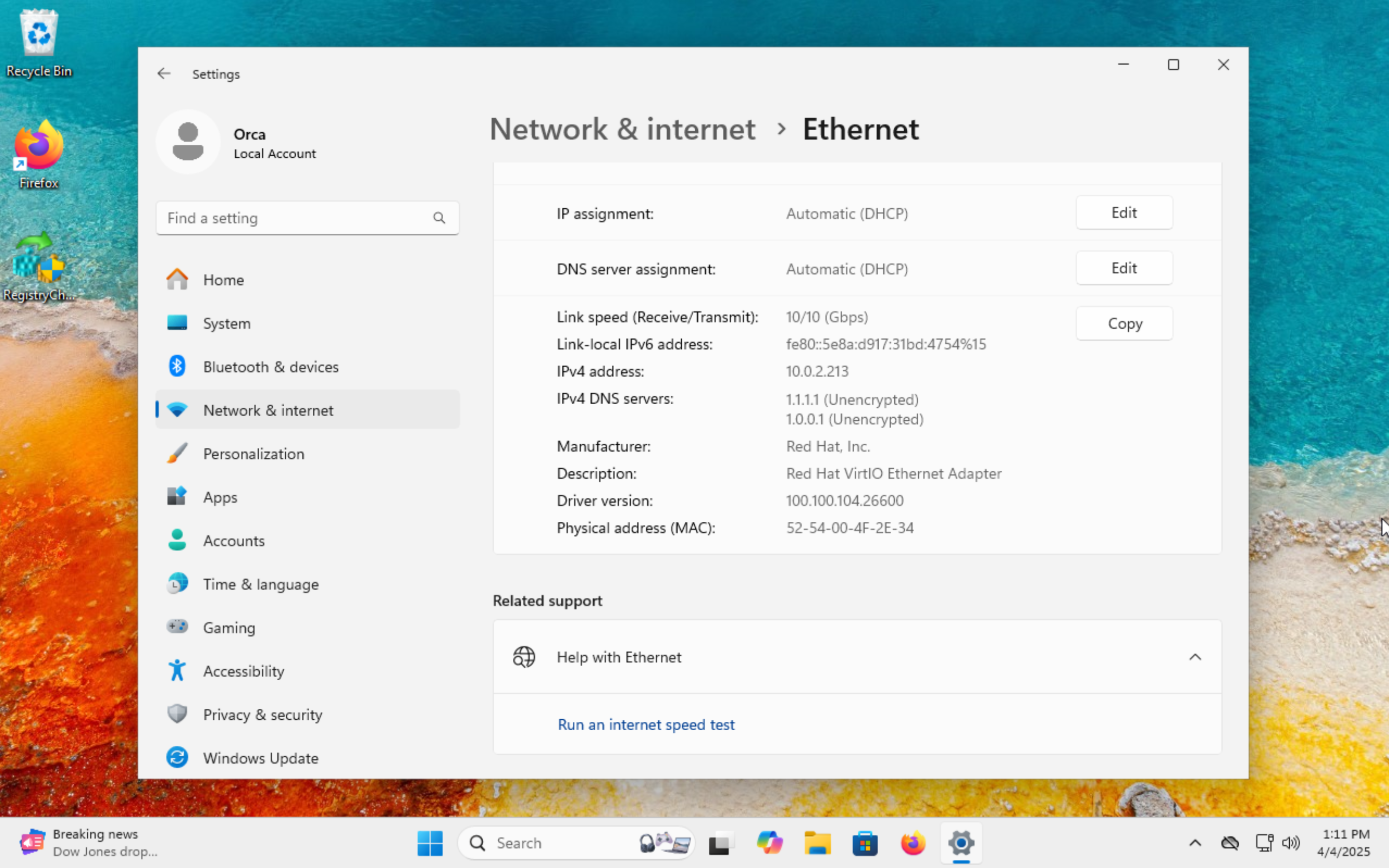
After the VM is fully booted, you'll see that it received an IP address from the network's DHCP server, and that it can communicate with other VMs in the network. In the screenshot above, the VM is attached to a 10.0.0.0/20 network, and was assigned 10.0.2.213 by DHCP.
To connect to services on a VM attached to a Disaster network, you can either use WireGuard, or set up port forwarding to distinct ports.
Info
As of today, changing the network settings after the VM has been created is not possible yet. We are working on this feature, but for now, you will need to delete the VM and create a new one with the correct network settings.
WireGuard VPN
When WireGuard is enabled, you can connect your laptop, phone, or router to the network. This allows you to access all VMs in the network as if they were on the local network. For example, after connecting, you'll be able to use RDP to connect to a Windows VM, or mount a Windows share from a file server.
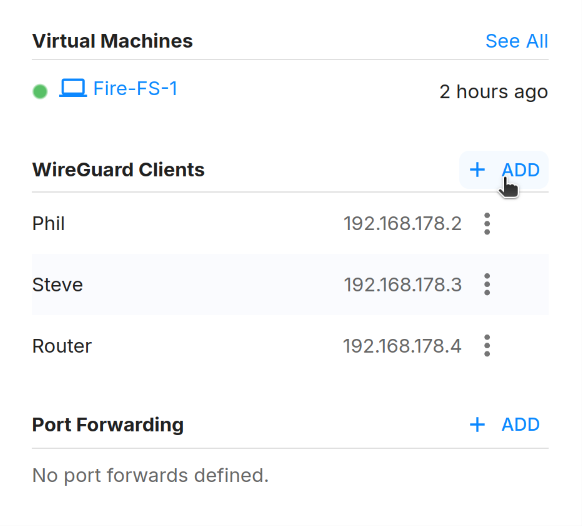
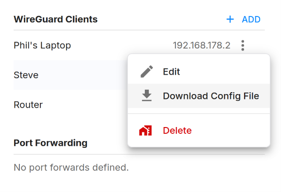
To connect your computer or phone to the Disaster Network, you need to create a WireGuard client. You can do this by clicking on the "Add" button in the sidebar of the network page.

Client Configuration
After adding a WireGuard peer in the Slide Console, download the configuration file and import into any of the WireGuard clients (Windows, macOS, Android, Linux). The configuration contains all the information needed to connect to the network, including the private key, public key, and endpoint address.
Here's an example of a WireGuard configuration file:
[Interface]
PrivateKey = yF5fwYIvyAfGG4j8eeyjnH/tkKstkSeLtOKfE6r2BHE=
Address = 192.168.178.3

[Peer]
PublicKey = nVoTvrB0h4Qi94kIE2BjJbf6e2NpbwZHVK4n8H7e2io=
AllowedIPs = 192.168.177.0/24, 192.168.178.0/24
Endpoint = use1-prod-gateway-1.slide.tech:33575
To configure your WireGuard VPN on Windows, download the config file and click "Add Tunnels":
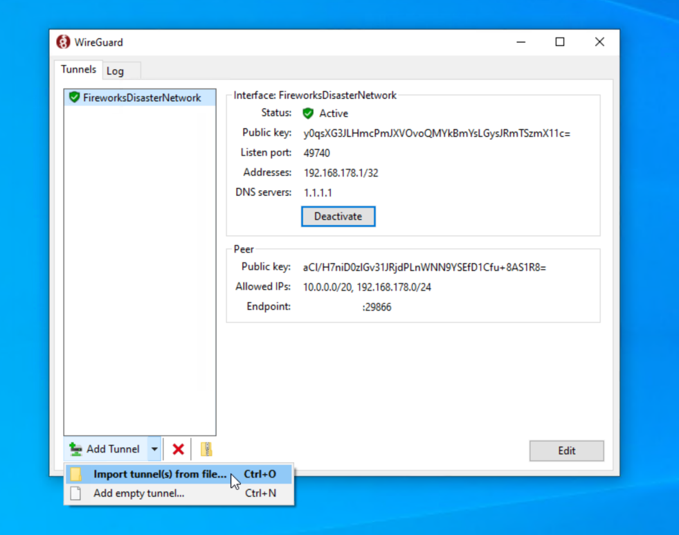
Once connected, you can reach any of the VMs using their internal IP address.
On Linux, place the config file in /etc/wireguard/mydisaster.conf and then use sudo wg-quick up mydisaster command to bring up the WireGuard interface.
Site-to-Site VPN
WireGuard can also be used to connect two sites if you have full control of the routing rules and WireGuard configuration on your local site.
Info
WireGuard-based site-to-site VPNs are not supported well on most firewalls/routers. Only use WireGuard site-to-site if you can modify routing rules and WireGuard configuration on your local gateway. Typically, it is best to use IPsec Site-to-Site VPN.
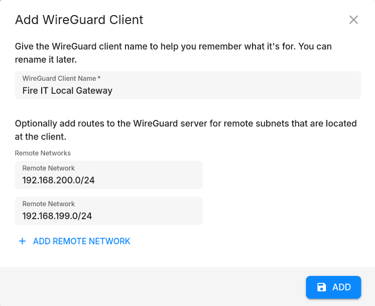
To set up a site-to-site VPN, click "Add Remote Network" when adding the WireGuard client through the Slide Console. This will add the remote networks to the allowed IPs of the WireGuard peer, allowing you to route traffic for these subnets through the VPN tunnel.
In the example below, traffic for 192.168.200.0/24 and 192.168.199.0/24 will be routed through the VPN tunnel to the remote networks. You can add as many remote networks as you need.
On your local router, you will need to set up a WireGuard peer that connects to the Slide Box's WireGuard server. In addition to that, you'll need to ensure that traffic for the Disaster Network is routed through the VPN tunnel.
IPsec Site-to-Site VPN
You can connect your local network to a Disaster Network using an IPsec site-to-site VPN, allowing machines from the LAN to seamlessly access VMs in the Disaster Network, and vice versa.
Almost all commercial routers and firewalls support IPsec site-to-site VPNs (e.g. Meraki, UniFi, SonicWall, etc.), so this is the recommended way to connect your local network to a Disaster Network.
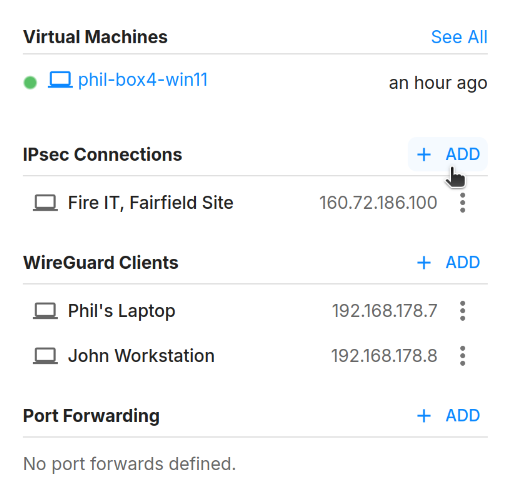
To add an IPsec site-to-site connection, click on the "Add" button in the sidebar of the network page. This will open a dialog where you can configure the IPsec connection settings.
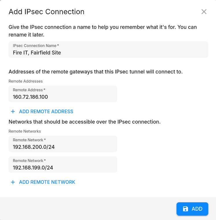
You will need to provide the following information:
- Name: The name of the connection.
- Remote IP Addresses: The public IP addresses of the remote router/firewall that you want to connect to. Typically, this is the public IP address of your client's router/firewall.
- Remote Networks: The network prefixes that you want to route through the VPN tunnel. This is typically the local network of your client's site (e.g. 192.168.200.0/24, 192.168.199.0/24, etc.).
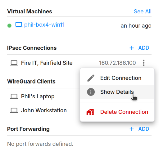
Once you click the "Add" button, the IPsec connection will be created and details of the connection can be accessed through the "Show Details" menu item from the sidebar. Important details such as the pre-shared key, remote and local authentication identifier will be displayed. You can copy these details to configure the remote router/firewall.
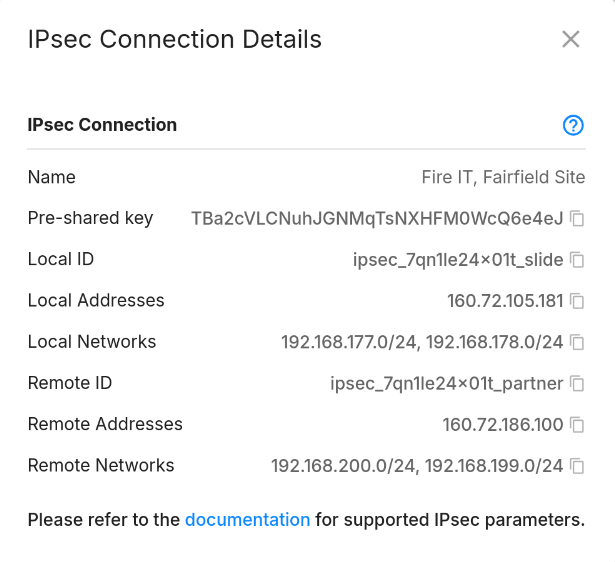
Information displayed in the details dialog includes:
- Name: The name of the connection.
- Pre-shared Key (PSK): The pre-shared key that you will need to configure on the remote router/firewall.
- Local ID: The local authentication identifier, ending in
_slide. This is the identifier used by the Slide network gateway. - Local Addresses: The public IP addresses of the Slide network gateway. This is the IP address that your router/firewall will connect to.
- Local Networks: The network prefixes of the Disaster Network that will be accessible through the VPN tunnel. This is the subnet of the Disaster Network and the subnet chosen for the WireGuard VPN (if enabled).
- Remote ID: The remote authentication identifier, ending in
_partner. This is the identifier used by your router/firewall. - Remote Addresses: The public IP addresses of the remote router/firewall that you configured in the "Remote IP Addresses" field.
- Remote Networks: The network prefixes that you configured in the "Remote Networks" field. These are the networks will be accessible through the VPN tunnel from the Disaster Network.
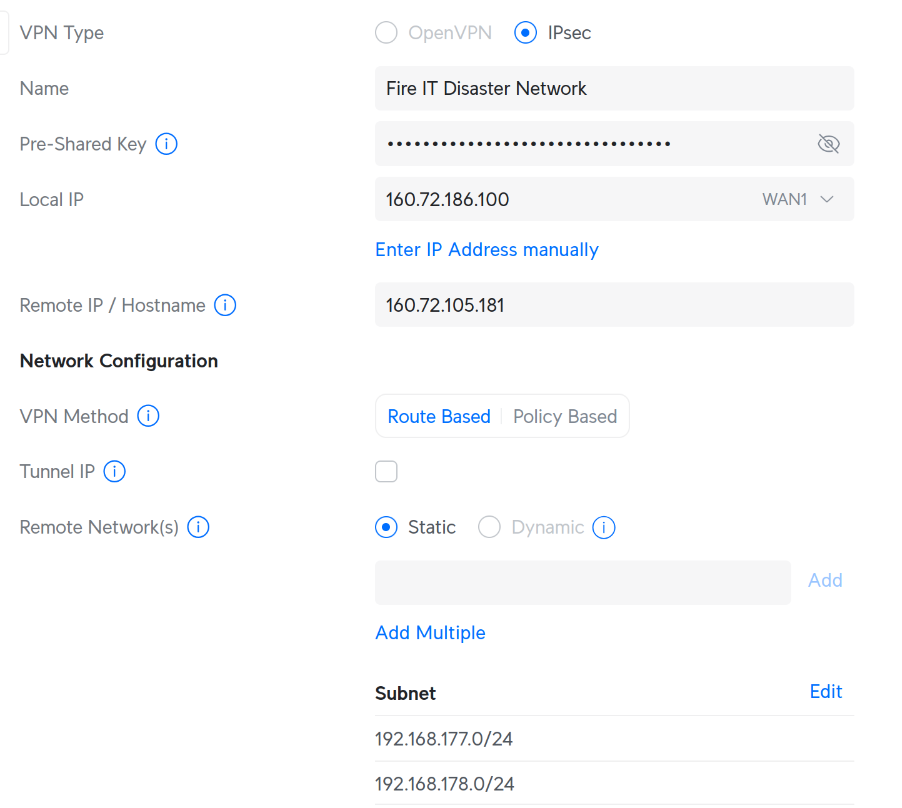
Configuring the Remote Router/Firewall
You will need to configure the remote router/firewall with the same settings, including the pre-shared key, encryption algorithm, and authentication method. The exact steps for configuring the remote router/firewall depend on the device you are using.
Here are some examples of popular devices:
Supported IKE/ESP proposals
When configuring the IPsec Site-to-Site on your router, you'll need to make sure that you choose supported IKE and ESP encryption, authentication and integrity algorithms, or your connection will fail. The Slide Disaster Network supports the following algorithms:
IKE:
- Version: IKEv2 only
- Authentication: Pre-shared key (PSK)
- Encryption: AES-256, AES-192, or AES-128
- Integrity: SHA-256, SHA-384, or SHA-512
- DH Groups: Curve25519 (31), ECP256 (19), MODP2048 (14), or MODP3072 (15)
ESP:
- Proposal Set 1 (AEAD): AES-256-GCM (128-bit ICV), AES-192-GCM (128-bit ICV), or AES-128-GCM (128-bit ICV)
- Proposal Set 2 (non-AEAD): AES-256, AES-192, or AES-128 with either one of SHA-256, SHA-384, or SHA-512
- DH Groups: Curve25519 (31), ECP256 (19), MODP2048 (14), or MODP3072 (15)
If you're using StrongSwan, you can use the following configuration:
proposals = aes256-aes192-aes128-sha256-sha384-sha512-curve25519-ecp256-modp2048-modp3072
esp_proposals = aes256gcm16-aes192gcm16-aes128gcm16-curve25519-ecp256-modp2048-modp3072, aes256-aes192-aes128-sha256-sha384-sha512-curve25519-ecp256-modp2048-modp3072
UniFi Dream Machine
Here's an example of how to configure an IPsec site-to-site VPN on a UniFi Dream Machine. The configuration is similar to the one described above but uses the UniFi interface to set up the connection.
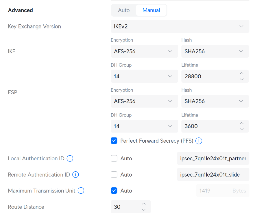
Things to note:
- Pre-Shared Key (PSK): UniFi automatically generates the pre-shared key. Be sure to replace it with the Slide-generated key.
- Local/Remote Authentication IDs: Click "Advanced", then select "Manual" to configure the Local and Remote Authentication IDs. The "Local Authentication ID" on your UniFi router is the one that ends in
_partner. The "Remote Authentication ID" on your UniFi router is the one that ends in_slide. This is the identifier used by the Slide network gateway. - IKE/ESP Proposals: UniFi supports a limited set of IKE and ESP proposals. Make sure to select the ones that are compatible with the Slide Disaster Network. The recommended settings are:
- IKE Version: IKEv2
- IKE Encryption: AES-256
- IKE Hash: SHA-256
- IKE DH Group: 14
- IKE Lifetime: 28800 seconds (8 hours)
- ESP Encryption: AES-256
- ESP Authentication: SHA-256
- ESP Lifetime: 3600 seconds (1 hour)
- ESP Hash: SHA-256
- ESP DH Group: 14
- Perfect Forward Secrecy: Enabled
Port Forwarding
Warning
By adding port forwarding for a service, you are exposing that service and the computer it is on to the Internet. This means that anyone can access the service using the public IP address and port. Be sure that you only expose services that you want to be publicly accessible.
It is always better to use WireGuard VPN or IPsec VPN to access services inside the disaster network. Port forwarding is only recommended for services that you want to be publicly accessible, such as web servers or file servers.
Port forwarding allows you to expose services on the VM to the Internet, e.g web servers or file servers. You can configure port forwarding in the network settings. To do so, select the network on the Networks page, and click "Add" in the "Port Forwarding" section.
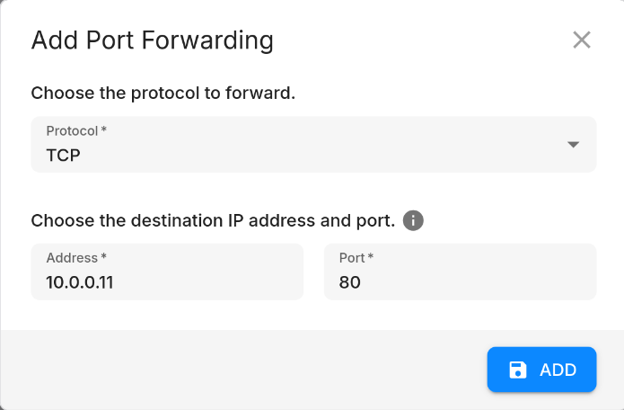
This will open a dialog where you can configure the port forwarding settings. You can choose TCP or UDP, and specify the destination IP address and port inside the network you want to forward to.
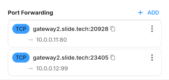
After you've added a port forward, you can copy the public IP address and port from the sidebar (e.g. gateway2.slide.tech:23405). This is the address you can use to access the service from the Internet.
Bridged Network
A Bridged Network creates a layer 2-only network across all the attached virtual machines, and then bridges all traffic to the Slide Box you select when creating the network.
Unlike the Disaster Network, a Bridged Network does not provide a router, DHCP server, or VPN access. Instead, it simply bridges the traffic to the local network of the Slide Box.
Virtual Machines attached to a Bridged Network will receive an IP address from the local router that the Slide Box is connected to. This means that you can use the same IP address range as your local network, and the VMs will be able to communicate with other devices on the local network.
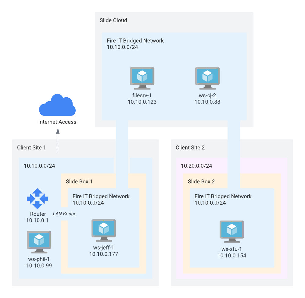
In the example above, the network at Client Site 1 (10.10.0.0/24) is bridged/extended to the Slide Cloud and both of the pictured Slide Boxes, meaning that all attached VMs will receive IP addresses from the router at Client Site 1 (here: 10.0.0.1). The VMs can communicate with each other, as well as with other devices on the local network.
Creating a Bridged Network
You can create a Bridged Network by clicking on the "Create Network" button in the top right corner:
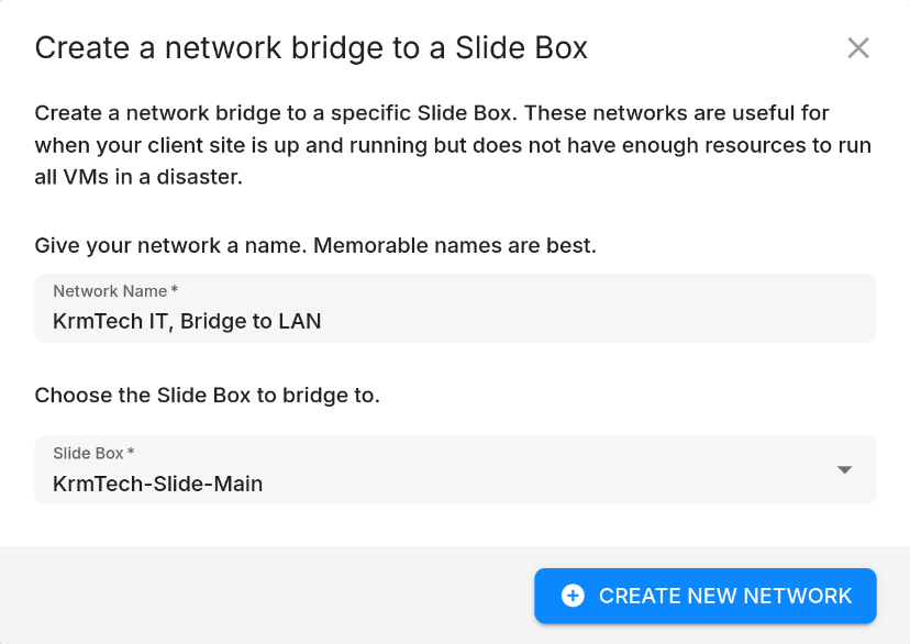
When creating a Bridged Network, you can specify the following options:
- Name: The name of the network.
- Slide Box: The Slide Box that this network is associated with. All VMs attached to this network will be bridged to the network that this Slide Box is connected to, even if they are spun up in the Slide Cloud or another Slide Box.
Attaching Virtual Machines
Attaching a VM works same way as when you attach VMs to a Disaster Network: Navigate to the restores page, create a new Virtual Machine, and select the Bridged Network you just created.
When the VM is booted up, it will receive an IP address from the local router that the Slide Box is connected to, even if it is running in the Slide Cloud.
Choosing Between Network Types
It may not be obvious when to use a Bridged Network, and when to use a Disaster Network. Here are some guidelines:
Choosing a Bridged Network
A Bridged Network will likely be beneficial to use when your client's site is still up and running, but the local Slide Box is not large enough to host all VMs required to get the customer back up and running so you need to run some virtualizations in the Slide Cloud.
Pros:
- Simple to set up
- No configuration needed on the local router
- Cloud VMs (or even VMs on other Slide Boxes) will receive an IP address from the local router's subnet
Cons:
- Only one entry/exit point from the network (the bridged Slide Box)
- All Internet-facing traffic from cloud VMs has to flow through the VPN tunnel and through the bridged Slide Box
- Not well suited for high-bandwidth applications
- Expands the local network's broadcast domain (e.g. ARP requests)
Choosing a Disaster Network
A Disaster Network should be used when in a full disaster where the local network and systems no longer exist or are expected to be unavailable for an extended period of time.
Pros:
- Dedicated subnet allows for more efficient routing
- Internet traffic can be routed directly to the Internet
- More suited for high-bandwidth applications
- Does not expand the local network's broadcast domain
Cons:
- More complex to set up
- Requires configuration on end clients and/or local router for WireGuard VPN
Use Cases
Use Case 1: Full site disaster
Scenario
The client site is completely destroyed, including all servers on the site and the Slide Box that was backing up the servers. In this example, we'll use ws-frontdesk-1 and filesrv-1 as example.
Solution
The destroyed servers are virtualized in the Slide Cloud and connected to a Disaster Network (10.0.0.0/24). All VMs are running in the Slide Cloud and receive IP addresses via DHCP (here: 10.0.0.102 and 10.0.0.123). A router (10.0.0.1) routes traffic to the Internet, between the VMs, or to the end client computers.
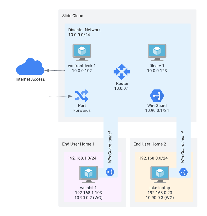
End users connect via WireGuard VPN to the Disaster Network, and can access the VMs as if they were on the local network. The end user computers receive IP addresses in the WireGuard network range (10.90.0.0/24). In the case above, ws-phil-1 is at 10.90.0.2, and jake-laptop at 10.90.0.3.
Use Case 2: Partial site disaster
Scenario
Some servers on the client site are destroyed. The Slide Box is still functional, but the resources on the Slide Box are not sufficient to run all virtualizations for all the lost machines.
The solutions below show two different approaches to this problem, one using a Bridged Network (solution A) and one using a Disaster Network (solution B). Please refer to the Choosing Between Network Types section for more information on when to use which network type.
Solution A
Some of the destroyed servers are virtualized on the Slide Box (sqlsrv-1), and some are virtualized in the Slide Cloud (filesrv-1 and termsrv-1). All VMs are attached to a Bridged Network, connected to the local network of the Slide Box. All VMs receive IP addresses from the local router, regardless of their location.
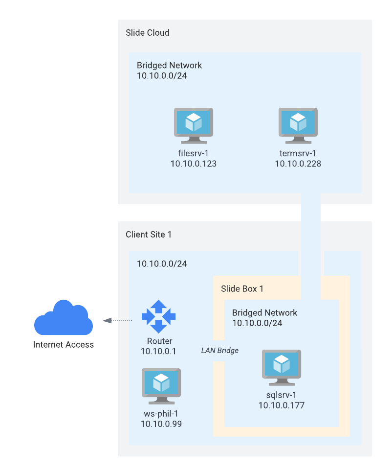
All Internet-facing traffic goes through the Slide Box. Port forwarding and DHCP must be provided on the local router.
Solution B
Some of the destroyed servers are virtualized on the Slide Box (sqlsrv-1), and some are virtualized in the Slide Cloud (filesrv-1 and termsrv-1).
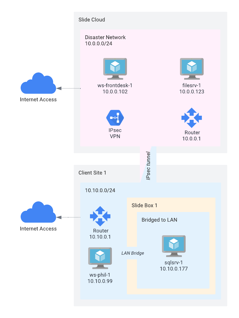
The two cloud VMs are attached to a Disaster Network in the 10.0.0.0/24 subnet. They receive IP addresses via DHCP (here: ws-frontdesk-1 at 10.0.0.102 and filesrv-1 at 10.0.0.23). Internet traffic is routed through the Disaster Network's router.
The VM running on the Slide Box is bridged to the local network of the Slide Box. It received an IP address from the local router (here: sqlsrv-1 at 10.10.0.177).
The two networks are connected via an IPsec Site-to-Site VPN and can communicate with each other seamlessly. The IPsec connection is configured on the local router, and routes traffic for 10.0.0.0/24 through the VPN tunnel towards the Disaster Network. The router in the Disaster Network routes traffic for 10.10.0.0/24 to the IPsec tunnel towards the local router.
Limitations
As of today, the following limitations apply to networks:
- Networks are only active when a VM is attached to them. Connecting to a network using WireGuard is only possible while a network is active.
- You cannot change the network settings of a VM after it has been created. You will need to delete the VM and create a new one with the correct network settings. We are working on this feature.